
The keyboard is a tool whose utility needs no introduction. Right now I using a keyboard to type this blog post. I find the keyboard to be an interesting device that deserves a look into how it works. By learning a little about the insides we can then plan to interface the keyboard with an FPGA and use it as an input device. I for one am really looking forward to learning how to drive VGA signals, and eventually making an FPGA based game that plays on a VGA monitor and uses keyboard as a controller. Until then, let’s start learning how to interface with the keyboard.
The keys on a keyboard have various purposes, with the majority being alphanumeric or symbol keys. There are also common modification keys, such as space, enter, shift, caps lock, backspace, etc. Many of the other key groups such as the F#, directional, and navigation keys serve special purposes within a computer system (i.e. Print Screen).
We will implement an FPGA keyboard interface that is simplified to process the alphanumeric & symbol keys, as well as the space, backspace, enter, tab, shift, and capslock keys. The keyboard used will have a PS2 connection, so we will need to implement a PS2 receiver circuit to receive scan codes from the keyboard when a key is pressed. We will then implement a keyboard interface circuit that processes the scan codes in a way that will make the keystroke responses natural and akin to how they would be in a simple text editor. Finally to test the keyboard circuit we will interface it with a UART transmitter to send the corresponding ASCII codes (converted from scan codes) to a PC serial monitor for viewing. This will allow us to type characters, words, and sentences, with the basic functionality of the text modification keys.

The PS2 interface is used for keyboards and mouses that connect to a PC host. While modern keyboards now use a USB connection to the host, we will focus on a keyboard using the PS2 interface, as the Basys 2 FPGA development board has one.
The PS2 port has two wires used for communication: a clock line, ps2c, and a data line, ps2d. Data is communicated in an 11-bit packet, with the data intended to sampled on the falling edge of the clock signal provided by the keyboard.

The data packet looks very similar to that used in a UART system, with the key difference being that it is sampled on the falling edge of a clock signal that only oscillates during data transmission. When no data is being transmitted, ps2d and ps2c are held high. When ps2c goes low for the start bit, the sampling of the packet begins. Eight data bits, one parity bit, and one stop bit are then sampled on the falling edge of ps2c. For our purposes we will only use the 8 data bits that are sampled, and ignore the parity bit for now.
Now that we have an understanding of the data protocol, lets look at the state machine diagram for the ps2 receiver. From the diagram, rectangles correspond to states, triangles to conditions, and ovals to variables that are adjusted.

The two states for the receiver are idle and rx (receive). In the idle state, if a negative edge is detected for ps2c, the start bit of a packet has been sent, if the receiver is also enabled, we go to the rx state. A counter variable n is set to 10 to count down for each remaining bit of ps2d we sample. In the rx state, if a negative edge for ps2c is detected, we sample ps2d by right shifting in the bit to the register d and then decrementing n. When n is equal to 0 we have sampled the 8 data, 1 parity, and 1 stop bits and are done, so we assert a one clock cycle done tick, and go back to the idle state.
Let’s look at the Verilog implementation:
module ps2_rx
	(
		input wire clk, reset,
		input wire ps2d, ps2c, rx_en,    // ps2 data and clock inputs, receive enable input
		output reg rx_done_tick,         // ps2 receive done tick
		output wire [7:0] rx_data        // data received
	);

	// FSMD state declaration
	localparam
		idle = 1'b0,
		rx   = 1'b1;

	// internal signal declaration
	reg state_reg, state_next;          // FSMD state register
	reg [7:0] filter_reg;               // shift register filter for ps2c
	wire [7:0] filter_next;             // next state value of ps2c filter register
	reg f_val_reg;                      // reg for ps2c filter value, either 1 or 0
	wire f_val_next;                    // next state for ps2c filter value
	reg [3:0] n_reg, n_next;            // register to keep track of bit number
	reg [10:0] d_reg, d_next;           // register to shift in rx data
	wire neg_edge;                      // negative edge of ps2c clock filter value

	// register for ps2c filter register and filter value
	always @(posedge clk, posedge reset)
		if (reset)
			begin
			filter_reg <= 0;
			f_val_reg  <= 0;
			end
		else
			begin
			filter_reg <= filter_next;
			f_val_reg  <= f_val_next;
			end

	// next state value of ps2c filter: right shift in current ps2c value to register
	assign filter_next = {ps2c, filter_reg[7:1]};

	// filter value next state, 1 if all bits are 1, 0 if all bits are 0, else no change
	assign f_val_next = (filter_reg == 8'b11111111) ? 1'b1 :
			    (filter_reg == 8'b00000000) ? 1'b0 :
			    f_val_reg;

	// negative edge of filter value: if current value is 1, and next state value is 0
	assign neg_edge = f_val_reg & ~f_val_next;

	// FSMD state, bit number, and data registers
	always @(posedge clk, posedge reset)
		if (reset)
			begin
			state_reg <= idle;
			n_reg <= 0;
			d_reg <= 0;
			end
		else
			begin
			state_reg <= state_next;
			n_reg <= n_next;
			d_reg <= d_next;
			end

	// FSMD next state logic
	always @*
		begin

		// defaults
		state_next = state_reg;
		rx_done_tick = 1'b0;
		n_next = n_reg;
		d_next = d_reg;

		case (state_reg)

			idle:
				if (neg_edge & rx_en)                 // start bit received
					begin
					n_next = 4'b1010;             // set bit count down to 10
					state_next = rx;              // go to rx state
					end

			rx:                                           // shift in 8 data, 1 parity, and 1 stop bit
				begin
				if (neg_edge)                         // if ps2c negative edge...
					begin
					d_next = {ps2d, d_reg[10:1]}; // sample ps2d, right shift into data register
					n_next = n_reg - 1;           // decrement bit count
					end

				if (n_reg==0)                         // after 10 bits shifted in, go to done state
                                        begin
					 rx_done_tick = 1'b1;         // assert dat received done tick
					 state_next = idle;           // go back to idle
					 end
				end
		endcase
		end

	assign rx_data = d_reg[8:1]; // output data bits
endmodule
The module ps2_rx has inputs for the clock, reset, ps2d, ps2c, and enable, with outputs for the done tick and received data.
To filter out any noise in the ps2c signal we use the 8-bit shift register filter_reg to shift in ps2c on each system clock cycle. Another 1-bit register, f_val_reg, has a next state value that is 1 when all 8 bits in the filter_reg are 1, or 0 when they are all 0. The f_val_reg doesn’t change for any other combination of 1’s and 0’s, so the ps2c signal will have to be stable and sampled for 8 clock cycles before changing.
The neg_edge signal is asserted when the current value in the f_val_reg is 1 and the next state is 0, meaning that a negative edge has arrived. This signal is used to trigger the transition from the idle state to the rx state, and to trigger a sampling of ps2d in the rx state.
Before we end the module we assign the portion of the d register that contains the received data bits to the output rx_data.
Now that we have a receiver circuit for the keyboard, we could interface it with a UART transmitter circuit to view the scan codes being sent from the keyboard. In fact I have done this, and it helped a lot in troubleshooting and developing the final keyboard interface implementation. If you plan on implementing the keyboard in another way, routing the scan codes to a UART receiver can be very instructive. Let’s continue on to explain the scan codes that we will receive from the keyboard and how to process them.
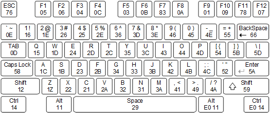
Image Source: reference.digilentinc.com
Each keyboard key has a unique hexadecimal code called a scan code. The scan codes for the basic keyboard keys are shown in the diagram above. Note that the scan codes are not ASCII codes. Some keys on the extended keyboard, such as the arrow keys, have two scan codes. The codes and clock signal are sent over the communication lines by a microcontroller inside the keyboard.
For example, if the A key is pressed and immediately let go, we will received the codes: 21 F0 21 . The code F0 is known as the break code and is sent when a key is let go, followed by a repeated scan code for the key.
Normally when you press and hold a key, the character begins to repeat. This is known as the typematic condition and usually begins after a key is held for a half second, upon which the scan code repeats at a frequency of 10 Hz. For example, the codes received for the T key being held for some time and then released are: 2C 2C … 2C F0 2C . In the typematic condition, the scan code of the held key repeats every 0.1 seconds, and when the key is released the break code is sent followed by the repeated scan code.
What if we hold a shift key and them press some characters? The first scan code will be 12 or 59 for the left or right shift key, followed by the normal scan codes for characters or symbols. For example, holding shift and typing “qwe”, then letting go of shift transmits the codes: 59 15 F0 15 1D F0 1D 24 F0 24 F0 59. If we were to use caps lock instead we would press caps lock once, then “qwe”, then caps lock again, which would send the codes: 58 F0 58 15 F0 15 1D F0 1D 24 F0 24 58 F0 58.
To process the scan codes and pass on the appropriate codes to an interfacing circuit to use, we will need to consider how to ignore break codes and the repeated scan codes after them, and how to handle shift and caps lock in order to convey uppercase keystrokes.
To implement the keyboard interface, we will design a FSM with 6 states: lowercase, ignore_break, shift, ignore_shift_break, capslock, ignore_caps_break. I made a state machine diagram that we will consider in portions, starting with the lowercase state.

In the lowercase state, if the signal scan_done_tick which is connected to rx_done_tick of ps2_rx is asserted, a scan code is ready to process. If it’s a shift key, go to the shift state, else if it is capslock, go to the capslock state, else if it is break, go to the ignore_break state, else set got_code_tick high. The got_code_tick signal will be routed out to the circuit that interfaces the keyboard and UART circuits, to let the uart_tx circuit know when to begin sending the appropriate data routed to it.
If we transition to the ignore_break state from lowercase, we just received a break code while sending scan codes out, so we need to ignore the incoming repeated scan code. To do this we simply wait for scan_done_tick to be asserted and then go back to the lowercase state.
Let’s briefly make sure things works so far. If we press the A key and then immediately let go, the lowercase state will process the first scan code C1, transition to ignore_break when F0 is received, and then ignore the final C1. This algorithm will work for the typematic case as well.
Let’s next consider when the state transitions from lowercase to shift after a shift key is pressed.

We first copy the scan code of the shift key to the register shift_type to keep track of which shift button was pressed. This will only allow us to go back to lowercase when the same shift key is let go. We will also set an output signal called letter_case to 1, which will let an outside circuit know to convert the scan codes we output into the uppercase ASCII code values. More on the conversion circuit later.
When in the shift state, if scan_done_tick is asserted, a scan code is ready from ps2_rx and we can process it. If the scan code is break, then we go to the ignore_shift_break state. If the scan code does not equal a shift or caps lock key we then assert got_code_tick to let the outer circuit know to convert the scan code received and use it, else we ignore the shift or caps lock key that was pressed.
In the ignore_shift_break we wait for scan_done_tick to be asserted when a scan code is received after the break code. We then check if the received scan code is the same as the shift key initially pressed, which means the same shift key was let go, so we go back to lowercase, else the scan code was a character or symbol key and we go back to the shift state to process more scan codes.
Finally let’s consider when we transition from lowercase to capslock.

Once again, since we will want uppercase ASCII codes to be interpreted outside the keyboard circuit while in the capslock state, we set letter_case to 1, which is normally 0. We also set a counter register called caps_num to 3. If we consider the scan codes received when we press capslock, then some character keys, then capslock again, we will transition from lowercase to capslock upon the first 58 (CAPS), upon which we will need to count 3 more occurrences of 58 before going back to lowercase: one for letting go of the first caps lock press, and two more for pressing and letting go of capslock again to exit the capslock state. Every time we get a scan code of 58 we will decrement caps_num, until 0, when we transition back to lowercase.
If caps_num isn’t 0, and a scan_done_tick is received from ps2_rx, if the scan code is 58 (CAPS), decrement caps_num, else if it is a break code we transition to the ignore_caps_break state, else if the scan code isn’t a shift key we assert got_done_tick, to output a scan code.
In the ignore_caps_break state, we wait for scan_done_tick to be asserted for a scan code received. If the scan code is CAPS, we then decrement caps_num, and transition back to capslock.

Above is the completed state machine diagram, click it to view. Below is the Verilog implementation for the keyboard interface circuit.
module keyboard

    (
	input wire clk, reset,
        input wire ps2d, ps2c,               // ps2 data and clock lines
        output wire [7:0] scan_code,         // scan_code received from keyboard to process
        output wire scan_code_ready,         // signal to outer control system to sample scan_code
        output wire letter_case_out          // output to determine if scan code is converted to lower or upper ascii code for a key
    );

    // constant declarations
    localparam  BREAK    = 8'hf0, // break code
                SHIFT1   = 8'h12, // first shift scan
                SHIFT2   = 8'h59, // second shift scan
                CAPS     = 8'h58; // caps lock

    // FSM symbolic states
    localparam [2:0] lowercase          = 3'b000, // idle, process lower case letters
                     ignore_break       = 3'b001, // ignore repeated scan code after break code -F0- reeived
                     shift              = 3'b010, // process uppercase letters for shift key held
                     ignore_shift_break = 3'b011, // check scan code after F0, either idle or go back to uppercase
		     capslock           = 3'b100, // process uppercase letter after capslock button pressed
		     ignore_caps_break  = 3'b101; // check scan code after F0, either ignore repeat, or decrement caps_num


    // internal signal declarations
    reg [2:0] state_reg, state_next;           // FSM state register and next state logic
    wire [7:0] scan_out;                       // scan code received from keyboard
    reg got_code_tick;                         // asserted to write current scan code received to FIFO
    wire scan_done_tick;                       // asserted to signal that ps2_rx has received a scan code
    reg letter_case;                           // 0 for lower case, 1 for uppercase, outputed to use when converting scan code to ascii
    reg [7:0] shift_type_reg, shift_type_next; // register to hold scan code for either of the shift keys or caps lock
    reg [1:0] caps_num_reg, caps_num_next;     // keeps track of number of capslock scan codes received in capslock state (3 before going back to lowecase state)

    // instantiate ps2 receiver
    ps2_rx ps2_rx_unit (.clk(clk), .reset(reset), .rx_en(1'b1), .ps2d(ps2d), .ps2c(ps2c), .rx_done_tick(scan_done_tick), .rx_data(scan_out));

	// FSM stat, shift_type, caps_num register
    always @(posedge clk, posedge reset)
        if (reset)
			begin
			state_reg      <= lowercase;
			shift_type_reg <= 0;
			caps_num_reg   <= 0;
			end
        else
			begin
                        state_reg      <= state_next;
			shift_type_reg <= shift_type_next;
			caps_num_reg   <= caps_num_next;
			end

    //FSM next state logic
    always @*
        begin

        // defaults
        got_code_tick   = 1'b0;
	letter_case     = 1'b0;
	caps_num_next   = caps_num_reg;
        shift_type_next = shift_type_reg;
        state_next      = state_reg;

        case(state_reg)

	    // state to process lowercase key strokes, go to uppercase state to process shift/capslock
            lowercase:
                begin
                if(scan_done_tick)                                                                    // if scan code received
		    begin
		    if(scan_out == SHIFT1 || scan_out == SHIFT2)                                      // if code is shift
		        begin
			shift_type_next = scan_out;                                                   // record which shift key was pressed
			state_next = shift;                                                           // go to shift state
			end

		    else if(scan_out == CAPS)                                                         // if code is capslock
		        begin
			caps_num_next = 2'b11;                                                        // set caps_num to 3, num of capslock scan codes to receive before going back to lowecase
			state_next = capslock;                                                        // go to capslock state
			end

		    else if (scan_out == BREAK)                                                       // else if code is break code
			state_next = ignore_break;                                                    // go to ignore_break state

		    else                                                                              // else if code is none of the above...
			got_code_tick = 1'b1;                                                         // assert got_code_tick to write scan_out to FIFO
		    end
                end

	    // state to ignore repeated scan code after break code FO received in lowercase state
            ignore_break:
                begin
                if(scan_done_tick)                                                                    // if scan code received,
                    state_next = lowercase;                                                           // go back to lowercase state
                end

	    // state to process scan codes after shift received in lowercase state
            shift:
                begin
                letter_case = 1'b1;                                                                   // routed out to convert scan code to upper value for a key

                if(scan_done_tick)                                                                    // if scan code received,
			begin
			if(scan_out == BREAK)                                                             // if code is break code
			    state_next = ignore_shift_break;                                              // go to ignore_shift_break state to ignore repeated scan code after F0

			else if(scan_out != SHIFT1 && scan_out != SHIFT2 && scan_out != CAPS)             // else if code is not shift/capslock
			    got_code_tick = 1'b1;                                                         // assert got_code_tick to write scan_out to FIFO
			end
		end

	     // state to ignore repeated scan code after break code F0 received in shift state
	     ignore_shift_break:
	         begin
		 if(scan_done_tick)                                                                // if scan code received
		     begin
		     if(scan_out == shift_type_reg)                                                // if scan code is shift key initially pressed
		         state_next = lowercase;                                                   // shift/capslock key unpressed, go back to lowercase state
		     else                                                                          // else repeated scan code received, go back to uppercase state
			 state_next = shift;
		     end
		 end

	     // state to process scan codes after capslock code received in lowecase state
	     capslock:
	         begin
		 letter_case = 1'b1;                                                               // routed out to convert scan code to upper value for a key

		 if(caps_num_reg == 0)                                                             // if capslock code received 3 times,
		     state_next = lowercase;                                                   // go back to lowecase state

		 if(scan_done_tick)                                                                // if scan code received
		     begin
		     if(scan_out == CAPS)                                                          // if code is capslock,
		         caps_num_next = caps_num_reg - 1;                                         // decrement caps_num

		     else if(scan_out == BREAK)                                                    // else if code is break, go to ignore_caps_break state
			 state_next = ignore_caps_break;

		     else if(scan_out != SHIFT1 && scan_out != SHIFT2)                             // else if code isn't a shift key
			 got_code_tick = 1'b1;                                                     // assert got_code_tick to write scan_out to FIFO
		     end
		 end

		 // state to ignore repeated scan code after break code F0 received in capslock state
		 ignore_caps_break:
		     begin
		     if(scan_done_tick)                                                                // if scan code received
		         begin
			 if(scan_out == CAPS)                                                          // if code is capslock
			     caps_num_next = caps_num_reg - 1;                                         // decrement caps_num
			 state_next = capslock;                                                        // return to capslock state
			 end
		     end

        endcase
        end

    // output, route letter_case to output to use during scan to ascii code conversion
    assign letter_case_out = letter_case;

    // output, route got_code_tick to out control circuit to signal when to sample scan_out
    assign scan_code_ready = got_code_tick;

    // route scan code data out
    assign scan_code = scan_out;

endmodule
Woo. Now lets take a breath, and consider the simpler task of converting scan codes to ASCII codes. Keyboards don’t send ASCII codes, and even send the same scan code regardless of a shift of caps lock being pressed. So we will need to derive a circuit that takes in a scan code and spits out an ASCII code. The circuit should also take a special 1-bit input denoting if the output should be uppercase, which we will route in from the output of the previous keyboard interface circuit.
module key2ascii
	(
		input wire letter_case,
		input wire [7:0] scan_code,
		output reg [7:0] ascii_code
	);

always @*
	begin
	if(letter_case == 1'b1)  // uppercase
		begin
		case(scan_code)
			8'h45: ascii_code = 8'h29;   // )
			8'h16: ascii_code = 8'h21;   // !
			8'h1e: ascii_code = 8'h40;   // @
			8'h26: ascii_code = 8'h23;   // #
			8'h25: ascii_code = 8'h24;   // $
			8'h2e: ascii_code = 8'h25;   // %
			8'h36: ascii_code = 8'h5E;   // ^
			8'h3d: ascii_code = 8'h26;   // &
			8'h3e: ascii_code = 8'h2A;   // *
			8'h46: ascii_code = 8'h28;   // (
			8'h1c: ascii_code = 8'h41;   // A
			8'h32: ascii_code = 8'h42;   // B
			8'h21: ascii_code = 8'h43;   // C
			8'h23: ascii_code = 8'h44;   // D
			8'h24: ascii_code = 8'h45;   // E
			8'h2b: ascii_code = 8'h46;   // F
			8'h34: ascii_code = 8'h47;   // G
			8'h33: ascii_code = 8'h48;   // H
			8'h43: ascii_code = 8'h49;   // I
			8'h3b: ascii_code = 8'h4A;   // J
			8'h42: ascii_code = 8'h4B;   // K
			8'h4b: ascii_code = 8'h4C;   // L
			8'h3a: ascii_code = 8'h4D;   // M
			8'h31: ascii_code = 8'h4E;   // N
			8'h44: ascii_code = 8'h4F;   // O
			8'h4d: ascii_code = 8'h50;   // P
			8'h15: ascii_code = 8'h51;   // Q
			8'h2d: ascii_code = 8'h52;   // R
			8'h1b: ascii_code = 8'h53;   // S
			8'h2c: ascii_code = 8'h54;   // T
			8'h3c: ascii_code = 8'h55;   // U
			8'h2a: ascii_code = 8'h56;   // V
			8'h1d: ascii_code = 8'h57;   // W
			8'h22: ascii_code = 8'h58;   // X
			8'h35: ascii_code = 8'h59;   // Y
			8'h1a: ascii_code = 8'h5A;   // Z
			8'h0e: ascii_code = 8'h7E;   // ~
			8'h4e: ascii_code = 8'h5F;   // _
			8'h55: ascii_code = 8'h2B;   // +
			8'h54: ascii_code = 8'h7B;   // {
			8'h5b: ascii_code = 8'h7D;   // }
			8'h5d: ascii_code = 8'h7C;   // |
			8'h4c: ascii_code = 8'h3A;   // :
			8'h52: ascii_code = 8'h22;   // "
			8'h41: ascii_code = 8'h3C;   // <
			8'h49: ascii_code = 8'h3E;   // >
			8'h4a: ascii_code = 8'h3F;   // ?
			8'h29: ascii_code = 8'h20;   // space
			8'h5a: ascii_code = 8'h0D;   // enter
			8'h66: ascii_code = 8'h08;   // backspace
			8'h0D: ascii_code = 8'h09;   // horizontal tab

			default: ascii_code = 8'h2A; // *
		endcase
		end
	else   // lowercase
		begin
		case(scan_code)
			8'h45: ascii_code = 8'h30;   // 0
			8'h16: ascii_code = 8'h31;   // 1
			8'h1e: ascii_code = 8'h32;   // 2
			8'h26: ascii_code = 8'h33;   // 3
			8'h25: ascii_code = 8'h34;   // 4
			8'h2e: ascii_code = 8'h35;   // 5
			8'h36: ascii_code = 8'h36;   // 6
			8'h3d: ascii_code = 8'h37;   // 7
			8'h3e: ascii_code = 8'h38;   // 8
			8'h46: ascii_code = 8'h39;   // 9
			8'h1c: ascii_code = 8'h61;   // a
			8'h32: ascii_code = 8'h62;   // b
			8'h21: ascii_code = 8'h63;   // c
			8'h23: ascii_code = 8'h64;   // d
			8'h24: ascii_code = 8'h65;   // e
			8'h2b: ascii_code = 8'h66;   // f
			8'h34: ascii_code = 8'h67;   // g
			8'h33: ascii_code = 8'h68;   // h
			8'h43: ascii_code = 8'h69;   // i
			8'h3b: ascii_code = 8'h6A;   // j
			8'h42: ascii_code = 8'h6B;   // k
			8'h4b: ascii_code = 8'h6C;   // l
			8'h3a: ascii_code = 8'h6D;   // m
			8'h31: ascii_code = 8'h6E;   // n
			8'h44: ascii_code = 8'h6F;   // o
			8'h4d: ascii_code = 8'h70;   // p
			8'h15: ascii_code = 8'h71;   // q
			8'h2d: ascii_code = 8'h72;   // r
			8'h1b: ascii_code = 8'h73;   // s
			8'h2c: ascii_code = 8'h74;   // t
			8'h3c: ascii_code = 8'h75;   // u
			8'h2a: ascii_code = 8'h76;   // v
			8'h1d: ascii_code = 8'h77;   // w
			8'h22: ascii_code = 8'h78;   // x
			8'h35: ascii_code = 8'h79;   // y
			8'h1a: ascii_code = 8'h7A;   // z
			8'h0e: ascii_code = 8'h60;   // `
			8'h4e: ascii_code = 8'h2D;   // -
			8'h55: ascii_code = 8'h3D;   // =
			8'h54: ascii_code = 8'h5B;   // [
			8'h5b: ascii_code = 8'h5D;   // ]
			8'h5d: ascii_code = 8'h5C;   // \
			8'h4c: ascii_code = 8'h3B;   // ;
			8'h52: ascii_code = 8'h27;   // '
			8'h41: ascii_code = 8'h2C;   // ,
			8'h49: ascii_code = 8'h2E;   // .
			8'h4a: ascii_code = 8'h2F;   // /
			8'h29: ascii_code = 8'h20;   // space
			8'h5a: ascii_code = 8'h0D;   // enter
			8'h66: ascii_code = 8'h08;   // backspace
			8'h0D: ascii_code = 8'h09;   // horizontal tab

			default: ascii_code = 8'h2A; // *
		endcase
		end
	end
endmodule
Finally to wrap things up we will design a circuit to interface the keyboard, key2ascii, and uart_tx circuit in order to send ASCII codes to a PC Serial monitor for viewing.
module key2uart
	(
		input wire clk, reset,
		input wire ps2d, ps2c,
		output wire tx
	);

	// signal declaration
	wire [7:0] scan_code, ascii_code;
	wire scan_code_ready;
	wire letter_case;
	reg  [7:0] r_reg;                       // baud rate generator register
	wire [7:0] r_next;                      // baud rate generator next state logic
	wire tick;                              // baud tick for uart_rx & uart_tx

	// instantiate keyboard scan code circuit
	keyboard kb_unit (.clk(clk), .reset(reset), .ps2d(ps2d), .ps2c(ps2c),
			 .scan_code(scan_code), .scan_code_ready(scan_code_ready), .letter_case_out(letter_case));

	// instantiate uart tx
	uart_tx tx_unit (.clk(clk), .reset(reset), .tx_start(scan_code_ready),
			.baud_tick(tick), .tx_data(ascii_code), .tx_done_tick(), .tx(tx));

	// instantiate key-to-ascii code conversion circuit
	key2ascii k2a_unit (.letter_case(letter_case), .scan_code(scan_code), .ascii_code(ascii_code));

	// register for oversampling baud rate generator
	always @(posedge clk, posedge reset)
		if(reset)
			r_reg <= 0;
		else
			r_reg <= r_next;

	// next state logic, mod 163 counter
	assign r_next = r_reg == 163 ? 0 : r_reg + 1;

	// tick high once every 163 clock cycles, for 19200 baud
	assign tick = r_reg == 163 ? 1 : 0;

endmodule
We instantiate the uart_tx circuit which I previously detailed here . We route from the scan_code and letter_case of the instantiated keyboard circuit to the instantiated key2ascii circuit to directly convert the scan code. The scan_code_ready signal is routed from the keyboard circuit to uart_rx’s tx_start input which starts transmitting the ASCII code when the keyboard circuit signals that a scan_code is ready to use. We also include the baud_tick circuit that is necessary to drive uart_tx at 19200 baud.
Above is a (lame) video demonstrating very basic use of the keyboard with the test circuit.
The Verilog code files and UCF file can be found here.

I have noticed you don’t monetize your blog, don’t waste
your traffic, you can earn additional bucks every
month because you’ve got high quality content. If you want to know how to make extra $$$,
search for: Ercannou’s essential adsense alternative
LikeLike
Can you please explain in detail that how a filter circuit work for ps2c.
It will be very helpful for my project since I strucked at that point.
Waiting for your reply..
LikeLike
I have a problem in the keyboard reciever circuit you have put the control box for n=n-1 before the decision box for n==0 .the microoperation n=n-1 will only occur when we go to the next state i.e when the clock forces transitions from the state recieve to another state.(be it recieve state itself or any other state in the machine).So your condition will always be checked a state later that means you are going to push in an extra bit if a negative edge does occur .Please correct me if im wrong
LikeLike
I loved what you did here, but I was wondering if you could help me with a problem. The ps2 keyboard I’m using is allways sending 0xFF. I realized that it’s a command that indicates there’s an error but I don’t even know why.
LikeLike
I want to save the data I received from the keyboard with these codes, but I can save the first data. When I receive the second data, an error occurs. What could be the reason. How can I do it
LikeLike